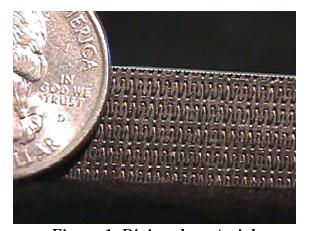
Porous materials are often used for the injector face plate of liquid propellant rocket engines. Fuel bleeds through the porous plate to aid in cooling of the injector face by transpiration while helping injection of fuel at the same time. For example, in P&W's RL10 engine and Space Shuttle Main Engine (SSME), Rigimesh is used. Rigimesh is formed by pressing layers of sintered stainless steel wire meshes. Rigimesh can qualitatively be classified as a dense, non-uniform, fibrous porous media.
|
|
|
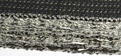
| Rigimesh material cross section | Rigimesh Schematic |
THE RL-10 PROPULSION SYSTEM
The injector, part of the thrust chamber assembly, featured a porous injector face, which was an important innovation. The RL-10 injector strongly resembled a large dish with a shallow, concave surface. Fabricated from material that looked like a heavy screen, the injector's propellant orifices poked through the mesh in concentric rings. The porous injector face did, in fact, consist of layers of stainless steel mesh, produced by a carefully controlled sintering procedure that caused the layers of mesh to become a coherent structure without melting. A controlled flow of gaseous hydrogen filtered through, cooling the injector face and reducing thermal stresses. The material, called Rigi-Mesh by its supplier (the Pall Corporation), apparently originated as a filter used in nuclear research. The product had been extensively used in hydraulic and pneumatic filters in aircraft and jet engines, where extreme vibration environments, high temperatures, and other operational requirements discouraged the use of nonmetallic filters. How Rigi-Mesh was first suggested for use in rocket thrust chambers is unclear. In any case, the Pratt & Whitney injector approach, using the porous mesh face, was a distinct improvement over conventional, flat-face injectors that Lewis Research Center had used.
THE J-2: LEGACIES AND INNOVATIONS
For the integrated engine system philosophy, designers of the J-2 borrowed from many earlier liquid propellant engines, including the liquid hydrogen technology of the RL-10 program, and added a few innovations along the way.
Like the RL-10, the J-2 injector had to promote stable, controlled burning. But the 890 000-newton (200 000-pound) thrust J-2 burned [145] much greater quantities of cryogenic propellants than the 67 000-newton (15 000-pound) thrust RL-10. When Rocketdyne started work on the injector in 1960, the company tried a design familiar to its engineers, and built flat-faced copper injectors similar to LOX-RP-1 designs. The heat fluxes of LOX-LH2 designs turned out to be much different at the injector face, and the injectors started burning out. Bob Pease, an MSFC propulsion engineer who monitored some of the early tests, recalled that green flames shot out of one injector as the flame front started burning its way through the copper.
As one Marshall engineer observed, it was the general nature of a contractor to be reluctant to take on a competitor's innovation. Rocketdyne's injectors kept burning out, but the company seemed adamant against incorporating the porous injector face style of Pratt & Whitney's RL-10. Rocketdyne had been experimenting with this type of injector at NASA's insistence, and Marshall began to feel that their J-2 contractor needed a shove in this direction, instead of the persistent nudges delivered by MSFC up to this point. Lewis Research Center had all the information and hardware samples for the porous injector face. Jerry Thomson and other Marshall engineers dragooned Rocketdyne personnel into a special trip to Lewis in 1962 to look at the samples, and pressured Rocketdyne to use Rigi-Mesh in the injector face. With Rigi-Mesh adapted to the J-2, the problems of injector face burning disappeared.
Still, Rocketdyne's larger engine and its operational characteristics presented difficulties in manufacturing. The successful design led to the next set of problems: how to "mass produce" a rocket engine injector with more than 600 uniform injection posts. After some trial and error, manufacturing engineers finally evolved a method of producing an injector with 614 uniform posts from a single piece of metal, using a special technique of electrical discharge machining. Fuel from the upper fuel manifold flowed into the combustion area through fuel orifices designed to be concentric with the oxidizer orifices. Design of the injector and angles of the orifices was calculated for highest combustion efficiency. As the hydrogen passed through the injector to the annular orifices, 5 percent of the flow seeped through the porous injector face, acting as a coolant to reduce thermal stresses created by the roaring combustion chamber.
Rigimesh is formed by pressing layers of steel wire meshes. Thus, a Rigimesh plate is denser towards the faces
making porosity smaller. We mentioned before that in the case of SSME, a Rigimesh plate with about 9% void
space is used. This implies substantial acceleration of flow inside the pores. Thus, the compressibility effect is likely
to become significant. These issues will be address in future efforts.